Tube crossover board circuit based on and 50 similar items

Tube crossover board circuit based on Marantz model 3 + daughter boards
View full item details »

Shipping options
$10.49 CAD to Worldwide
Ships from
Hong Kong

Offer policy
OBO - Seller accepts offers on this item.
Details
Return policy
Full refund available for DOAs
Purchase protection
Payment options
PayPal accepted
PayPal Credit accepted
Venmo accepted
PayPal, MasterCard, Visa, Discover, and American Express accepted
Maestro accepted
Amazon Pay accepted
Nuvei accepted
View full item details »
Shipping options
$10.49 CAD to Worldwide
Ships from
Hong Kong
Offer policy
OBO - Seller accepts offers on this item.
Details
Return policy
Full refund available for DOAs
Purchase protection
Payment options
PayPal accepted
PayPal Credit accepted
Venmo accepted
PayPal, MasterCard, Visa, Discover, and American Express accepted
Maestro accepted
Amazon Pay accepted
Nuvei accepted
Item traits
| Category: | |
|---|---|
| Quantity Available: |
Only one in stock, order soon |
| Condition: |
New |
| UPC: |
Does not apply |
| Brand: |
Unbranded/Generic |
| MPN: |
Does Not Apply |
Listing details
| Shipping discount: |
No combined shipping offered |
|---|---|
| Posted for sale: |
More than a week ago |
| Item number: |
1555541968 |
Item description
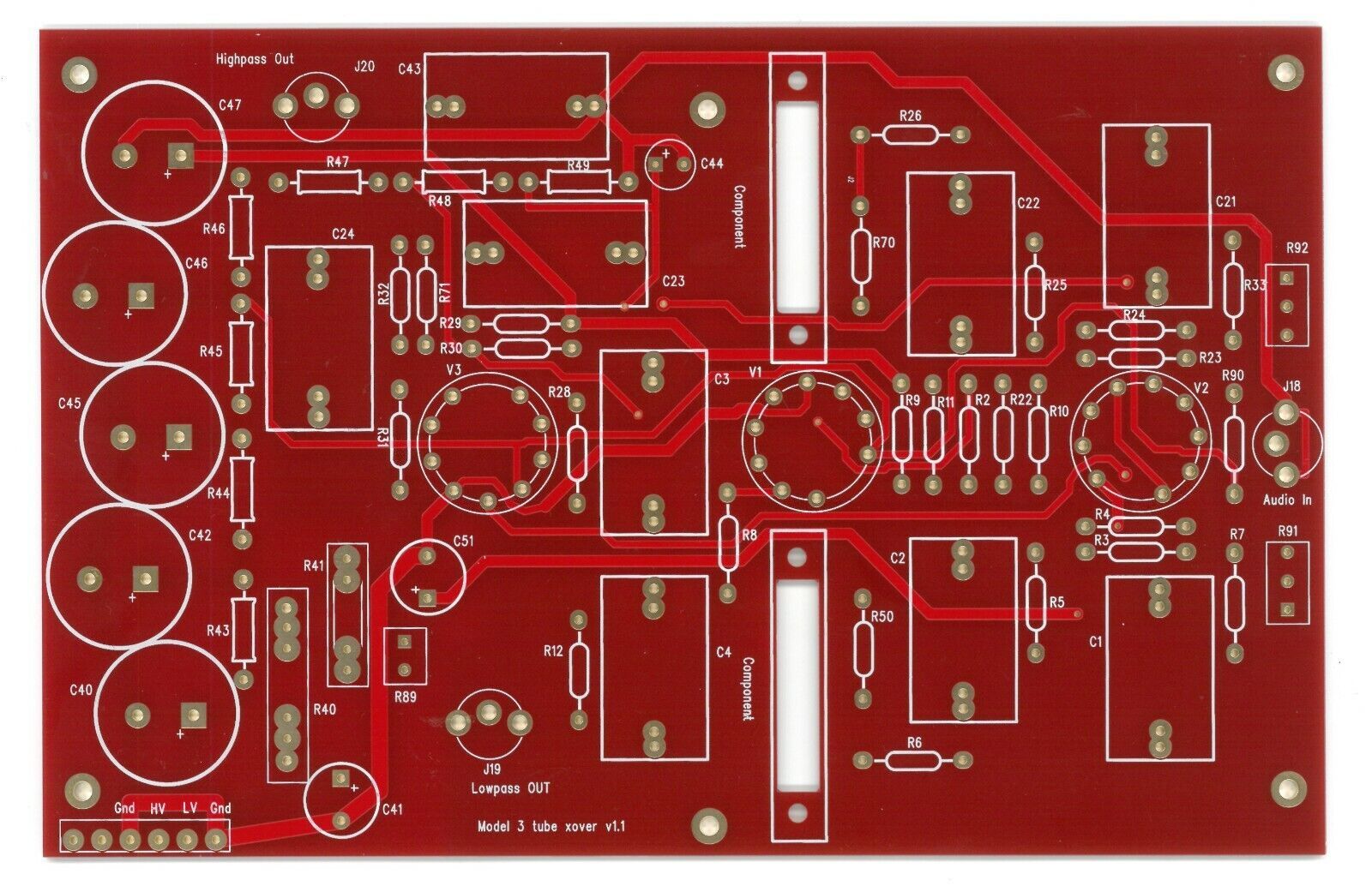
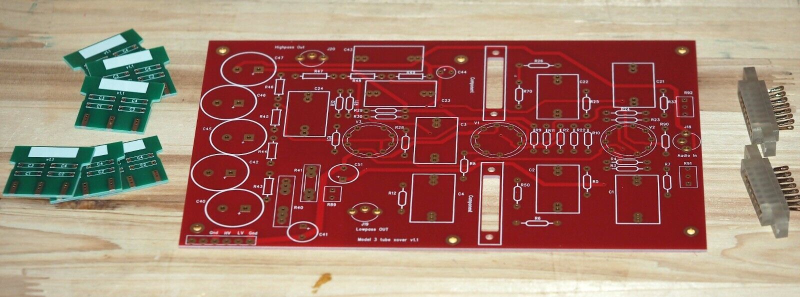
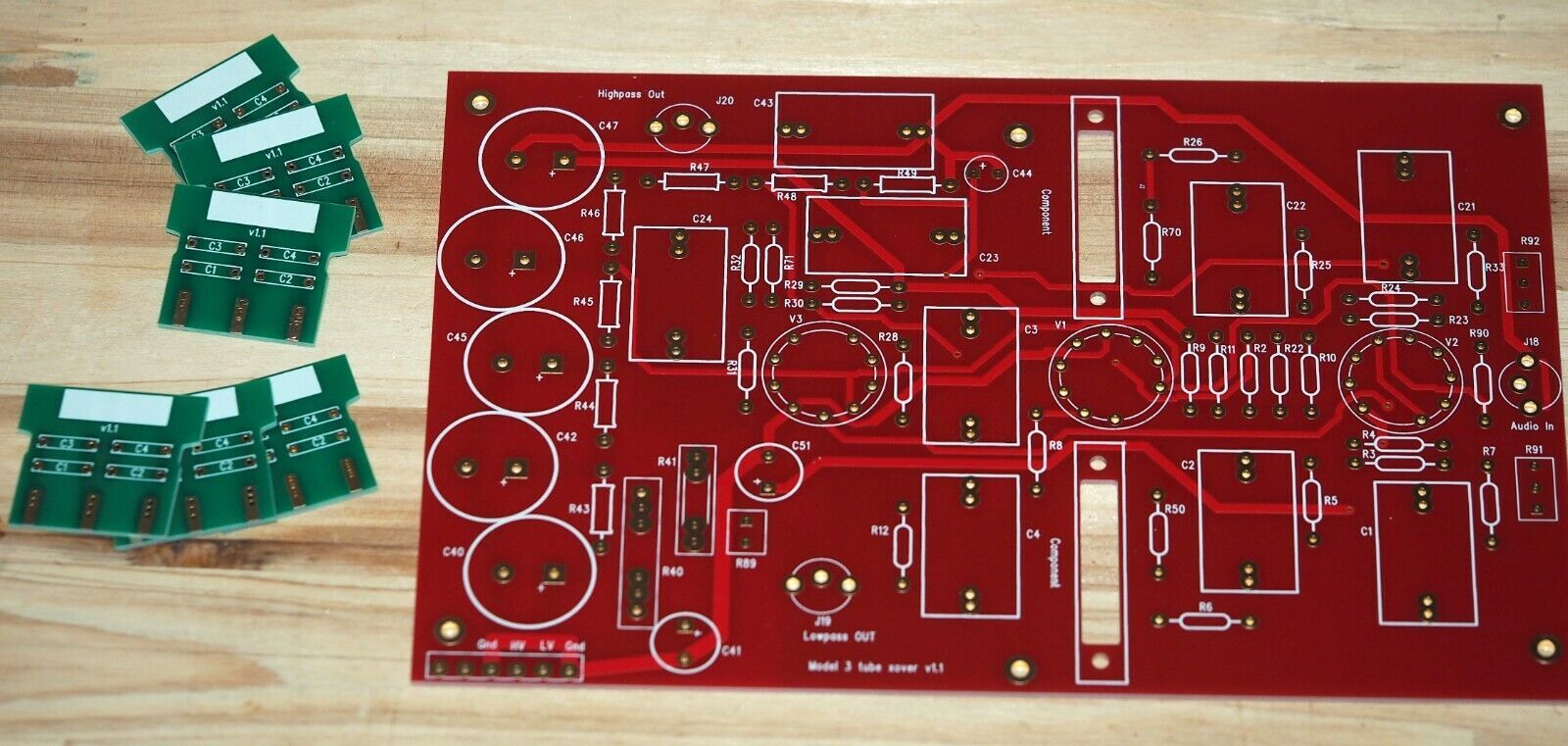
This is the bare PCB of a tube crossover board , circuit based on legendary Marantz model 3.
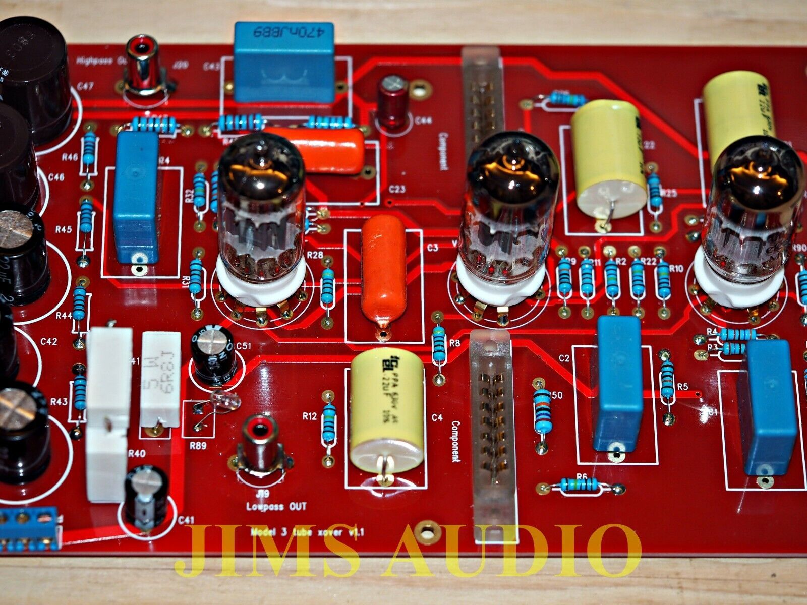
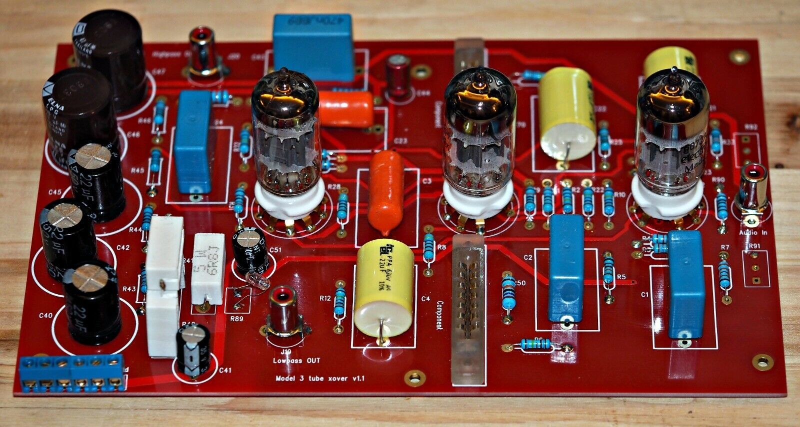
The circuit is a 6dB/oct 2-way crossover design, using three 12AX7 ( or three 12AY7, or 1 12AU7 and 2 12AX7). 6dB/oct gives a most natural roll off and musical performance on listening. Original Marantz users manual recommended users to use different frequencies for the high pass and low pass section to suit various speaker design. This is a prophetic idea at the time when electronic crossover was just emerging. Nowadays crossovers used to set high and low to have the same frequency but this is not necessarily the best sound to our ears.
In this incarnation, we use daughter cards to change the crossover frequencies, instead of rotary switch, as rotary switch extended to the front panel can deter the sound by the switch contacts and long signal wires from switch to the board.
We follow the original design to include light bulb circuit so users can build their chassis with the bulb included as the power indicator.
This listing includes one main board, three pairs of daughter boards, two daughter boards sockets and a light bulb.
For users wanting more daughter boards, there is another listing to order them.
We provide schematic, part list and a frequency table for the capacitors on the daughter boards.
Each board contains one audio channel that branches into the high pass and low pass output. For stereo application, two boards are needed.
PCB dimension : 147mm x 228mm.
PCB thickness : 1.6mm
Copper thickness : 70um( 4 times standard copper thickness !)
Supply voltages : 1. DC 250V - 280V DC 20mA , 2 DC 28V 500mA
We do air shipping worldwide at US$7.50. We welcome combine shipping.
Track Page Views With
Auctiva's FREE Counter
Powered by SoldEazy
|
Why are we showing these items?
Booth
JIMS AUDIO |

|


-
Refine your browsing experience
We can show you more items that are exactly like the original item, or we can show you items that are similar in spirit. By default we show you a mix.


This item has been added to your cart
 Tube crossover board circuit based on Marantz model 3 + daughter boards added to cart.
Only one available in stock
Tube crossover board circuit based on Marantz model 3 + daughter boards added to cart.
Only one available in stock
View Cart or continue shopping.
 Please wait while we finish adding this item to your cart.
Get an item reminder
We'll email you a link to your item now and follow up with a single reminder (if you'd like one). That's it! No spam, no hassle.
Already have an account?
Log in and add this item to your wish list.